#1MPB Metalworking Projects and Plans Book.(Volume 1- Benches)

$39.00
#1MPB Metalworking Projects and Plans Book.(Volume 1- Benches)
 Support USA jobs. Buy Better built tools
 made in our country.
Description
Below is an example for Volume 1 Tables. This book gives the same detailed instructions for Benches
(256 pages)

The next few pages show instructions for forming 3/16”x 1.5” flat stock (which makes up the outer perimeter) around any of the 30”x 30” square coffee table designs shown in this book.
NOTE: All the plasma cut designs in this book, whether they’re drawings or completed tables, come from PlasmaCam’s art package entitled “Exquisite Tables.” The particular table shown below, from that art package, happens to be called “Exuberant Elephant.”
These forming instructions are the same no matter which one of the square table top designs you use as long as the artwork itself is cut to 30”x 30”. The added frame will increase the overall size of the table by 3/8 of an inch. Instructions for forming various base designs, including the one seen on this table using Shop Outfitters’ tools can be seen in the table plan book shown above.

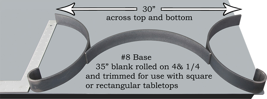
Regardless of which one of the 30”x 30” Square Tabletop Designs you wish to make, the instructions will be the same as those shown for making the “Exuberant Elephant” table. Some of the bases that are designed to fit the 30”x 30” square tables will also fit the 30”x 42” rectangular tables. If the two base assemblies that are used on this base are used on one of the rectangular tables then it may be necessary to add a couple of cross ties between the two ends.
These square tables can easily be scaled up to make a patio or dining room table. Doing so will require coming up with an adequate table leg support base that four chairs can fit easily under. You may decide to make one of the square or rectangular tables a little smaller or larger than the 30” standard width ones. Remember, if you do, you will need to use a different die size to form all four corners of the perimeter frame. This will require some experimenting in order to determine what that die size is, as well as the new blank length of the perimeter frame material to be formed. None of that will be necessary as long as you stay with fabricating the standard size table designs shown in this book.
When you’re ready to paint one of these finished tables, powder coating durability is hard to beat. Powder coating also tends to build up on edges that are a little sharper than they should be. This will blunt these edges more than they would be as compared with painting them with an inferior paint from an aerosol spray can. However, your work should still be sanded smooth so you’re not relying on the blunting characteristics of the powder coating. There are a lot of great looking finishes available from most commercial powder coating shops, including various hammer tones.
When it comes time to get the glass for your table, you’ll need to find a professional glass cutter. Be sure the outside edge is rounded smooth so no one gets cut on it. Use tempered glass when possible. If you decide to use a thicker glass than 1/4”, such as 3/8”, then you will need to allow for the extra thickness when you’re fabricating the table. This will require spacing the plasma cut artwork up off of the welding table with 1/2” nuts rather than 3/8” nuts (shown in the instructions) before welding the perimeter frame to the table top. The top edge of the glass should be flush or slightly below the perimeter frame which will help protect it from getting damaged. It’s also a good idea to put a few small inconspicuous felt or rubber pads between the steel table top and the glass.
Cut out any of the 30” Square Tabletop Designs on your PlasmaCam cutting machine from their art disk entitled “Exquisite Tables.” The recommended material thickness for any of these tables is 10 or 11 gauge. Anything lighter is not recommended. The artwork should be cut from clean rust free steel sheets. The artwork will pick up considerable rigidity once the outer rim is welded to it. If there is any light flashing left on the bottom side of the artwork after it’s cut, be sure to sand it off before welding the outer rim to the outer perimeter of the tabletop.
Cut (4) pieces of 3/16”x 1.5” hot rolled flat 30” long. Lightly sand any sharp edges off of all the ends so you or anyone else does not get cut while you’re working with them.
Set the Lock-N-Stop Gauge on 21+ and tighten the Lock Handle. Various mill runs of steel will sometimes bend a little different than others. Each time you set the Lock-N-Stop Gauge on a new setting, check the first bend before repeating it on more of the same parts. You may need to slightly increase or decrease the setting to get the angle desired. In spite of mill run differences, the settings in this book should all be close, having all been tested.

Set the Stop Block in the B position as shown here to the right. Remember to place the Support Pin under it. Place the other dies in their correct positions as seen in the bottom photo. The positions for all three pins that hold the Center Die, Follower Die, and Stop Block can be seen below inserted in their proper holes.
Place one of the (4) 30” long material pieces in the bender as shown below. Rotate the Bending Handle around until the 3” Follower Die just touches against the material. Slide the material endwise until the end (shown below) measures 10” from the Stop Block. NOTE: The Stop Block Measurement is always the distance from the end of the part to the closest face of the Stop Block.

Bend the material around the 3/4” round tubing die by rotating the Bending Handle clockwise until it rests firmly against the Stop Pin. The Spring Pin should be fully depressed into the Stop Pin to complete the bend as shown below.
NOTE: The 3/4” round tubing die is used to make the corner radius for both the 30” square tables and the 30”x 42” rectangular tables. If they are scaled up or down in size, then a different die size will have to be used to make the perimeter frame in order to match the radius of each corner of the plasma cut artwork.
Next, rotate the bending handle counterclockwise all the way to the back position and remove the part. Check the bent part with a framing square to make sure the bend is somewhere near 90 degrees after being formed. If it needs a little more or less bend angle, adjust the Lock-N-Stop Gauge slightly before making the next bend on the remaining parts. Don’t try to reset the gauge by re-bending the first part you formed. This is because the bent part will not bend the same the second time it’s inserted into the bender. If the finished bends are only slightly off of 90 degrees, usually they can be pulled into place and clamped to the artwork for welding without a problem.

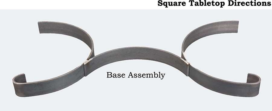
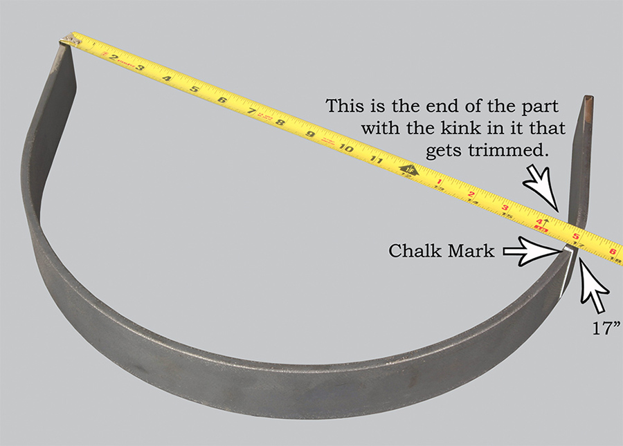
Lay the plasma cut artwork on the welding table with the side that was facing up in the cutting machine now face down. Lay two of the pieces, you just bent, on the table up against the outside edge of the artwork as shown below. One of the pieces will overlap the other one. With both of the pieces tight against the artwork, on both the right and left side, put a chalk mark at the joint as seen at the bottom of this page.

Once the piece with the chalk mark on it has been trimmed off, fit the two pieces back together tight against the table top. Tack weld the two bent pieces together, but not to the table top. Use a couple of C vise grips to clamp the material tight against the top, on three sides, when you tack weld the ends together. Next, add the third bent piece to the next corner. Mark and trim the overlap the same as you did on the first two bent pieces. Repeat the process on the last corner. When you’re done you will have completed the perimeter frame less the finished welding. Next, tip up the frame and clamp it down on one of its four individual sides for final welding and sanding as seen in the bottom photo. One at a time, weld, grind, and sand all four sides of the frame both inside and out.
NOTE: You can space the artwork up from the table and weld the four parts to each other and the artwork without removing the frame. However, it is easier to grind the frame smooth if it’s removed.

Once the frame joints have all been welded and ground smooth, the table top can be slid back into the frame and spaced off of the welding table with a dozen or so 3/8 inch standard nuts as shown below. This will give you the right spacing on the opposite side so that 1/4” glass (tempered if possible) will set slightly below the top surface of the perimeter frame.

Be sure the frame is down tight against the welding table and is clamped tight against the table top artwork all the way around. Next, place three welds, about a half inch long, along all four sides of the inside of the perimeter frame as seen below.
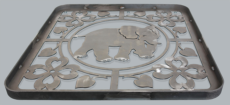
Once you’ve finished welding the perimeter frame to the artwork and you flip it right side up for examination, it should look like this.

çStep #10 When you’ve completed the top shown above, and have flipped it back over with the top side facing the table, you will be ready to weld the base of your choice to the underside of the table as shown on the opposite page. In the case of this elephant table, we decided to use the base design seen below. Instructions for making the various bases start on page 68.
These two base assemblies are welded square with the table and recessed about 1/4 of an inch down from the bottom edge of the perimeter frame. They are welded 5” in from each end of the frame. You will need to place removeable blocking under the leg bases to hold them up for welding in position. It’s also helpful to clamp a couple of bars across the bottom of the two legs in order to keep them parallel with each other as well as square with the table while you’re welding them in place.

These tables can be made to look quite different from each other, depending on which base assembly you decide to use with it, as seen on pages 14 thru 19. You may even want to come up with one of your own base designs. Adding ornamental formed scrolls as part of the base can also give the table a nice look. Care should be taken to not make the bases look busy by adding too many scrolls. When scrolls are used in the bases they should enhance the artwork in the tops, which are the main focus, but not detract from them.
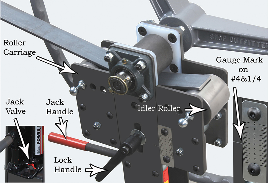
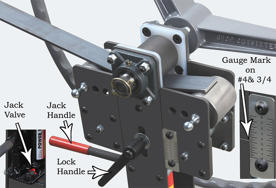
Place one of the pieces into the #338 Pedestal Ring Roller until it protrudes just past the center of the roller. With the Lock Handle loosened and the Jack Valve tightened, crank the Jack Handle until the Gauge Mark is on #4& 3/4. This will put a kink in the end of the part which will be cut off later. Tighten the Lock Handle. Roll the material through the roller as seen on the next page. Roll the remaining (3) pieces of flat stock following the same sequence of actions as was done on the first rolled leg.


Make (4) Arched Curl Legs as per the instructions that are shown on pages 144 thru 149.
Cut (2) pieces of 1/4”x 2” hot rolled flat stock 35” long and sand both ends, removing any sharp edges. Place one of them in the #338 Pedestal Ring Roller with one end protruding slightly past the center of the bottom right Idler Roller. With the Jack Valve tightened, crank the Jack Handle until the gauge mark is on 4&1/4. This will put a kink in the end of the part that will be trimmed off later. Roll the part all the way through the roller. Loosen the Jack Valve and lower the Roller Carriage.NOTE: It’s not necessary to tighten the Lock Handle each time material of this thickness or lighter is rolled through the machine. The Lock handle is used more for square tubing or heavy bar stock where there is a lot of back pressure on the jack. Repeat the rolling process with the other piece.